
Last Updated: November 5, 2026
Quick Summary
CAM software reduces scrap and rework by moving the decision point upstream, where nesting, digitizing and file conversion errors are caught before fabric is cut. Automated nesting raises material use, and camera-based digitizing plus standardized file formats prevent the errors that surface as rework at the cutting table.
- Most scrap in a sewn-product factory is a file problem that shows up at the cutting table.
- True-shape nesting of curved pieces is often the single biggest material-use lever.
- Test a nesting engine on one plain, one large-repeat print and one napped style.
- CAM software prevents file, nesting and conversion defects but not fixture or operator variation.
- Record your material-use figure and rework rate per style before any vendor demo.
Table of Contents
- Why Scrap and Rework Start Before the Cutter Runs
- What CAM Software Does in a Sewn-Product Workflow
- How Fabric Nesting Software Raises Material Use
- Pattern Digitizing Software: Fixing Accuracy at the Source
- How to Reduce Material Waste in Manufacturing with a Repeatable Process
- Pattern File Conversion Software and the Errors It Prevents
- A Practical Framework for Evaluating CAM Software
- Request a Free Material Test Cut or Digitizing Sample
- Frequently Asked Questions
Why Scrap and Rework Start Before the Cutter Runs
Most scrap in a sewn-product factory is not a cutting problem. It is a file problem that shows up at the cutting table.
A badly nested marker, a pattern digitized a few millimeters off, or a DXF that lost its layers in conversion all look like operator error once the fabric is on the table. By then the material is spent.
What CAM Software Does in a Sewn-Product Workflow
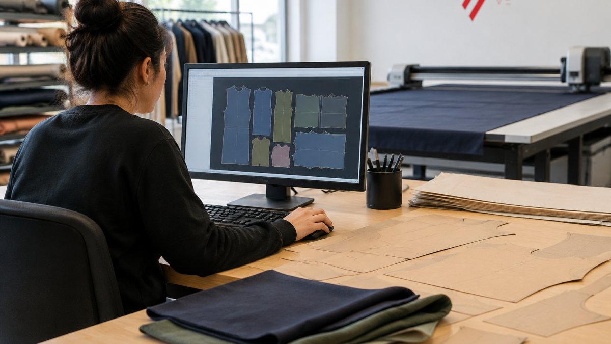
CAM software is the layer that turns a design file into production instructions a machine can execute. In sewn products, that means pattern design, grading, marker making, nesting, and the output files that drive plotters and cutters.
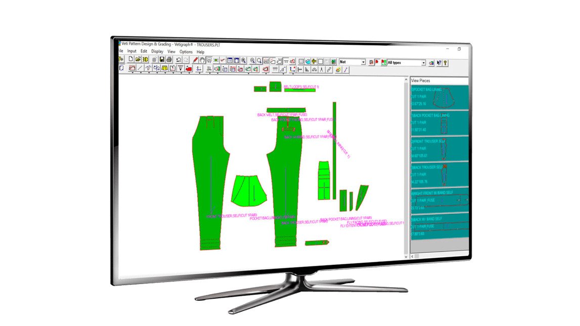
The workflow runs in a fixed order, and each step inherits the errors of the one before it:

- Digitize existing paper patterns into DXF, AAMA DXF or PLT files
- Design and grade patterns in CAD
- Nest pieces into a marker that uses the least material
- Plot the marker on paper for verification and the cutting room
- Cut production material on an automatic cutter
Complete Guide to Computer-Aided Manufacturing describes simulation and verification as ways to catch programming problems before they reach the floor, which is the same logic that applies here: verify on paper before you commit fabric.
That logic is why we sell the workflow as four connected product lines rather than one machine. A plotter that prints a marker accurately is worthless if the nesting behind it wasted material, and a cutter that holds tolerance is wasted if the pattern it follows was digitized badly. The Vetigraph CAD and nesting software page covers the pattern, grading and marker modules.
How Fabric Nesting Software Raises Material Use
Fabric nesting software decides how pieces sit on the marker. That single decision drives most of your material use and is where the largest waste reductions are available. But the difference between a good result and a wasteful one usually lives in the settings, not the demo.
Automated nesting can test many more layouts than manual marker making, rotating and flipping pieces and applying matching rules for striped, plaid and printed fabrics with distortion compensation.
What actually changes the material-use figure
- True-shape versus bounding-box placement. An engine that nests the actual outline of a curved piece can tuck pieces into gaps that a rectangle-based engine leaves empty. On curved garment and upholstery parts, this is often the single biggest lever.
- Gap and buffer settings. The space between pieces is a tolerance decision, not a default. Too tight and the cutter or plotter drifts into the next piece; too loose and you give away material on every marker. Set it per material, not once for the shop.
- Grain-line and directional constraints. Nap, pile, one-way prints and stretch direction all restrict rotation. The engine must honor those constraints while still searching, an engine that quietly ignores grain line will report a great use figure and produce an unusable marker.
- Matching rules for patterned fabric. Stripe and plaid matching forces pieces into alignment bands. Distortion compensation lets the engine absorb small repeat drift instead of forcing a perfect match that wastes a full repeat per marker.
- Marker length versus ply count. A shorter marker is not always the cheaper one. On a fixed table length, a slightly longer marker that fits more plies can beat a tight marker that limits the lay.
How to test a nesting engine on your own fabric
Do not judge nesting software by one demo marker on a plain cotton. Run a controlled comparison instead:
- Pick three real styles: one plain fabric, one large-repeat print, and one napped or one-way fabric.
- Nest each style at your production sizes and record the material-use figure and marker length.
- Re-nest the same styles with a different engine or setting and compare the same two numbers.
- Plot both markers and lay them side by side on the table before cutting anything.
A common pattern is that engines converge on plain fabric and diverge sharply on the patterned and napped styles. That divergence is where your real savings or losses sit.
Watch out: an engine that reports a higher use figure but violates grain line or matching rules will look better on paper and fail in the cutting room.
For a deeper look at layout strategy, this guide on optimizing fabric nesting to cut material waste walks through the tactics in detail, and the Vetigraph CAD and nesting software page covers the marker and nesting modules we sell and support.
Pattern Digitizing Software: Fixing Accuracy at the Source
Pattern digitizing software converts a physical pattern into an editable digital file. If that conversion is inaccurate, every downstream step inherits the error, and no amount of careful nesting recovers it.
Manual digitizing on a tablet introduces small inconsistencies: a point placed slightly off, a curve that flattens, a seam allowance that drifts. Camera-based digitizing captures the pattern shape directly and exports DXF, AAMA DXF or PLT files.
The V-Shoot camera digitizing system is the tool we supply for this step, and it exports in the three formats CAD and nesting software expect. If your patterns are still on paper, this is the first place to fix accuracy, not the last.
How to Reduce Material Waste in Manufacturing with a Repeatable Process
Reducing material waste in manufacturing is a process problem, not a software purchase. The software only helps if the process around it is repeatable.
A practical sequence for a repeatable process:
- Digitize every active pattern and retire the paper originals from production use
- Standardize file formats so CAD, plotter and cutter all read the same source
- Nest before you plot, and review the marker on paper before approving it
- Record the use figure for each marker so you can compare layouts
- Cut only approved markers, so the cutting room never improvises
- Log every rework event and trace it back to a file, a setup, or an operator step
Logging each rework event makes its root cause easier to trace, whether it sits in a file format, a fabric, or a shift.
A practical rule: when a defect appears, ask whether the file was correct, the setup was correct, or the operator step was correct, in that order.
Pattern File Conversion Software and the Errors It Prevents
Pattern file conversion software translates CAD output into the format a plotter or cutter reads. Plotters read PLT, HPGL and HPG natively.
Common failures in conversion include:
Vetigraph – CAD Design and Nesting →
- Layers dropped during conversion, so a marker prints without its internal lines
- Scale drift, so a pattern plots slightly large or small
- Curve approximation that turns a smooth arc into segments
None of these announce themselves. They surface as a marker that doesn’t match the CAD screen, or pieces that fit badly after cutting.
Easy-Plot handles DXF, DWG and PDF conversion to PLT and HPGL, which keeps the plotter fed with files it reads natively and removes the manual workaround most shops invent.
A Practical Framework for Evaluating CAM Software
Evaluating CAM software on how it handles your worst case, rather than its best demo, is a sound principle.
Step 1: Establish a baseline before you demo anything
You cannot claim a scrap reduction you never measured. Before you talk to any vendor, pull the last few months of production and record:
- Your current material-use figure per style, from the marker or the cutting report
- Your rework and reject rate per style, and the defect types behind it
- Which defects trace back to a file, a setup, a tool, or an operator step
That baseline is the only honest comparison point. A vendor demo on sample files proves nothing about your fabric, your repeat, or your tolerances.
Step 2: Run a representative-part test, not a showcase
Give every candidate the same three real styles, one plain, one large-repeat print, one napped or one-way fabric, plus one pattern that is currently giving you trouble. Ask each vendor to digitize, nest, and plot those files and return the output. Then compare:
- Material-use figure and marker length against your baseline
- Whether the marker respects grain line and matching rules
- Whether the plotted marker matches the CAD screen at full size
- How long the vendor’s team took, and how many manual fixes were needed
Set acceptance criteria up front: a minimum improvement in use figure, zero format errors on your own files, and a marker you would actually approve. If a vendor cannot hit those on your parts, the feature list does not matter.
Step 3: Separate what CAM can fix from what it cannot
This distinction is important when judging whether software will pay back. When a defect appears, classify it before you blame the software:
| Defect symptom | Likely root cause | What actually fixes it |
|---|---|---|
| Marker uses more material than expected | Nesting settings or engine limits | Nesting rules, gap and buffer settings, engine choice |
| Pieces fit badly after cutting | Digitizing or grading error | Re-digitize, verify graded sizes, fix source file |
| Marker prints without internal lines | File conversion dropped layers | Conversion step, format standardization |
| Pattern plots slightly large or small | Scale drift in conversion | Verify plot scale against CAD, fix conversion settings |
| Cut edge wanders on some pieces | Fixture, material hold, or cutter setup | Setup and tooling changes, not CAM |
| Same defect on one shift only | Operator step or work instruction | Training, work instructions, shift standardization |
CAM software prevents the first four categories. The last two require changes to fixtures, tools, inspection, or work instructions, and no software purchase fixes them. Insist the vendor help you make this distinction during evaluation, because a vendor that promises to fix operator variation with a license is selling you the wrong thing.
Step 4: Close the loop between programming and inspection
A workflow that feeds results back can be stronger than one that only pushes files out. Such a loop works as follows:
- Program and nest in CAD
- Plot the marker and verify on paper before cutting
- Cut, then inspect the first pieces against spec
- Log any deviation against the file, setup, or operator step
- Correct the source and re-nest before the next run
That loop helps turn a one-time fix into a repeatable process.
Step 5: Count the full cost of ownership
Compare the whole picture, not the license: training time for pattern makers and cutting-room staff, any conversion software needed to feed the plotter or cutter, implementation and installation time, and the downtime during changeover.
DevOpsSchool’s manufacturing software discussion makes the honest point that software savings depend on process, part design and operator skill. Treat any vendor promising a fixed reduction without those caveats with suspicion.
For a ready-made checklist, this article on criteria for choosing CAD nesting software for upholstery applies the same framework to a specific material set.
Request a Free Material Test Cut or Digitizing Sample
The fastest way to settle whether CAM software reduces your scrap is to test it on your own material and patterns.
Free material test cuts and pattern digitizing samples are available so you can see the output before committing.
We install onsite in the Los Angeles area and handle remote installation and training elsewhere, so a small cutting room gets the same setup discipline as a large one.
Get started with Velocity Plotters and test the workflow on your own material before you change anything on the floor.
Frequently Asked Questions
How can CAM software reduce scrap and rework?
It reduces scrap in three places: at the file, at the marker, and at the machine. Accurate pattern files remove sizing and distortion errors before anything is cut. Automated nesting raises material utilization by rotating and flipping pieces to fit tighter. Simulation and verification catch programming problems before production starts. Research on computer-aided manufacturing notes that verifying jobs before they reach the floor helps eliminate rework and scrap, though the actual savings depend on your process, part design and operator skill.
What is the difference between CAD software and CAM software?
CAD covers design and pattern work: creating, editing and grading patterns. CAM covers manufacturing preparation: marker making, nesting, toolpath generation and the NC code that drives a cutter. In a sewn-product factory the two overlap heavily. Vetigraph, for example, handles pattern, grading, marker and nesting in one system, then outputs DXF, HPGL or ISO Cutfile for the plotter or cutter. Buyers should check which side of that line a package actually covers before comparing options.
How does nesting software reduce material waste?
Nesting software arranges pattern pieces on the marker to use as much of the material as possible. It rotates and flips pieces, tests many layout combinations, and accounts for stripe, plaid and print matching where needed. The gain shows up as a higher percentage of the roll becoming finished parts instead of offcuts. Because the software can test layouts far faster than a person with paper, it usually finds tighter markers on complex styles, where manual nesting leaves the most room.
How can manufacturers check pattern files before production?
Run three checks. First, confirm the file format matches what the machine reads natively: PLT and HPGL go straight to a plotter, while DXF and DWG need a conversion step. Second, plot the marker at full size on paper and measure key pieces against the spec. Third, run a test cut on the actual material before committing a full roll. A free material test cut or a digitizing sample lets you confirm accuracy on your own fabric rather than a demo sample.
The challenge is simple: pick one marker this month, nest it in software, plot it, and compare the utilization figure to your current layout. That single comparison tells you more than any demo. Velocity Plotters supports the full path from digitizing through plotting and cutting, with free test cuts, remote training, and financing through TimePayment. Get started with Velocity Plotters and see what your own material does.

 EN_US
 ES