

Introduction
Many companies in apparel, furniture, upholstery, footwear, automotive, and technical textiles still preserve a significant part of their production knowledge in physical patterns made of paper, cardboard, manila paper, fabric, or other materials.
These templates may represent years of experience and technical adjustments. However, they also have limitations: they deteriorate, take up physical space, are difficult to share, and may produce inconsistencies when copied or modified manually.
Learning how to digitize physical patterns for CAD software makes it possible to convert these templates into editable, reusable files that can be integrated into digital design, grading, marker making, plotting, and cutting workflows.
Velocity Plotters & Cutters offers an ecosystem that connects these stages. The V-Shoot Camera Digitizing System converts physical patterns into vector files, VetiGraph supports geometry review and editing, Easy-Plot helps convert selected files for output processes, and Velocity plotters and cutters bring the final digital pattern into production.
What Does It Mean to Digitize a Physical Pattern?
Digitizing is not simply taking a photograph or scanning a template.
The objective is to convert the contour, internal lines, and reference features of the pattern into vector information that CAD software can interpret and modify.
A properly prepared digital pattern may include:
- outer contour;
- internal lines;
- notches;
- perforations;
- reference points;
- seam allowances;
- material or grain direction;
- part name or code;
- size or measurement;
- cutting instructions;
- relationship to other components.
The main difference between an image and a digital pattern is that an image is made of pixels, while a CAD file contains editable lines, curves, and coordinates.
This allows users to modify dimensions, correct curves, perform grading, create variations, and later send the geometry to a plotter or digital cutting system.
Why Should Companies Digitize Their Patterns?
Pattern digitizing provides both technical and operational benefits.
Pattern Preservation
A physical template may become distorted due to humidity, use, folding, or poor storage. A digital file provides a preserved master version.
Greater Repeatability
The same pattern can be reproduced consistently without relying on a new manual copy.
Faster Editing
Dimensions, curves, seam allowances, and technical details can be adjusted directly in CAD software.
Better Version Control
The company can identify which file is approved, when it was modified, and which product or production line uses it.
Production Integration
The pattern can be connected to nesting, marker making, plotting, and automated cutting.
Less Dependence on Physical Storage
Templates can be stored, backed up, and shared without moving paper or cardboard pieces between locations.
1. Inspect and Prepare the Physical Pattern
Before digitizing, inspect the template carefully.
The pattern should be placed as flat as possible and checked for:
- folded edges;
- tears;
- distortion;
- faint lines;
- perforations;
- notches;
- written references;
- areas that require correction.
It is also advisable to clean the pattern and confirm that it is the version the company wants to preserve.
Digitizing an incorrect or outdated template will simply transfer those problems into the CAD environment.
When there is uncertainty about a critical dimension, measure it manually before capture so it can later be used as a validation reference.
2. Select the Right Digitizing Method
Different methods can be used to convert physical patterns into digital files.
Manual Digitizing Table
The operator records points along the contour using a digitizing table. This method can be accurate, but it often requires more time and operator training.
Large-Format Scanner
A scanner can work well for selected pieces, but pattern size is limited by the available scanning area and may require several images to be combined.
Camera-Based Capture and Automatic Vectorization
This method uses a camera to capture the pattern and software to detect, correct, and convert the contour into vector information.
The V-Shoot Camera Digitizing System uses photographic capture and automatic vectorization to transform physical patterns into files prepared for CAD software. It can export formats such as DXF, AAMA DXF, and PLT for integration with common CAD workflows across different industries.
3. Position the Pattern Correctly on the Capture Surface
Pattern placement directly affects the quality of the result.
The pattern should be:
- completely visible;
- free of folds;
- unobstructed;
- clearly contrasted against the background;
- positioned inside the system’s recognized area;
- secured to prevent movement.
V-Shoot uses a surface with visual references that allow the software to correct optical distortion caused by camera distance, angle, and position. The system may also use a magnetic base to hold patterns in place without adhesive tape.
For better contrast:
- use a dark background for light-colored patterns;
- use a light background for dark patterns;
- avoid strong shadows;
- use uniform lighting;
- do not cover calibration markers.
4. Capture the Pattern Image
Once the pattern is positioned correctly, the image can be captured with a compatible camera.
Depending on the setup, this may include:
- a mounted camera;
- a DSLR camera;
- a compatible mobile device;
- manual capture from a controlled position.
V-Shoot is designed to automatically correct perspective and scale using the printed references on its surface. This means the camera does not necessarily have to remain permanently fixed over the board.
For large patterns, a V-Shoot XL configuration or a sectional digitizing process may be used to capture oversized templates.
5. Automatically Vectorize the Pattern Contour
After the image is captured, the software detects the pattern and converts its geometry into vector lines.
Vectorization may recognize elements such as:
- contours;
- corners;
- curves;
- perforations;
- notches;
- internal lines;
- mirrored shapes.
V-Shoot automates image capture and vectorization, reducing the need to manually record every point along the pattern.
However, automatic processing does not eliminate the need for human review. The operator should confirm that:
- the contour is closed;
- there are no duplicate lines;
- curves are correct;
- notches are properly identified;
- perforations are in the correct position;
- shadows or unwanted marks were not captured as geometry.
6. Validate the File Scale
One of the most important steps is verifying that the digital pattern maintains a true 1:1 relationship with the physical template.
A known dimension can be used for validation:
1. Measure a critical distance on the physical pattern.
2. Open the digital file.
3. Measure the same distance in the software.
4. Compare both values.
5. Correct the scale if there is a difference.
V-Shoot uses calibration references to generate full-scale measurements and correct capture distortion.
Before sending the pattern into production, it is also advisable to print or cut a validation sample.
7. Export the Pattern in a Compatible Format
The correct file format will depend on the CAD software and output equipment used later in the workflow.
Common formats include:
- DXF;
- AAMA DXF;
- PLT;
- HPGL;
- SVG, depending on the workflow.
V-Shoot can export files in DXF, AAMA DXF, and PLT formats, helping connect digitized patterns with CAD systems used in fashion, furniture, automotive, and industrial design.
Before exporting, confirm:
- required file format;
- units of measurement;
- scale;
- DXF version;
- layer handling;
- support for notches and perforations;
- pattern orientation.
8. Import the File into CAD Software
Once the file has been generated, it can be opened in CAD software for technical preparation.
Velocity offers VetiGraph CAD, a solution for pattern creation, editing, grading, and marker preparation. VetiGraph systems allow users to create patterns, apply technical adjustments, and prepare designs for production within a digital workflow.
At this stage, users can:
- correct lines and curves;
- remove unnecessary points;
- close contours;
- add seam allowances;
- insert notches;
- add perforations;
- mirror pieces;
- adjust dimensions;
- create sizes;
- add part codes;
- prepare the pattern for nesting.
9. Clean and Correct the Geometry
Although automatic capture speeds up the process, a final cleanup is still recommended.
Common actions include:
- reducing excessive points;
- smoothing curves;
- joining segments;
- removing duplicate lines;
- checking angles;
- confirming symmetry;
- reviewing corners;
- correcting small defects from the original pattern.
A file with too many points can be harder to edit and may create unnecessary cutting movements.
The goal is to preserve the correct shape using clean and efficient geometry.
10. Add Technical Production Information
A digital pattern should include all the information required to reduce interpretation during later production stages.
This may include:
- part name;
- product code;
- size;
- cutting quantity;
- material;
- grain or material direction;
- seam allowance;
- assembly reference;
- revision;
- date;
- customer or collection;
- required operation.
This information improves organization and reduces the risk of using the wrong pattern.
11. Perform Grading When Required
In fashion, apparel, footwear, and other industries, multiple sizes or measurements may need to be generated from a base pattern.
Grading involves increasing or decreasing selected sections while preserving defined proportions and rules.
VetiGraph can be used for pattern creation, editing, and grading inside its CAD environment.
Before grading, confirm that the base pattern is correct. Any error in the original piece will be reproduced across all derived sizes.
12. Prepare a Marker or Nesting Layout
Once the parts are ready, they can be arranged within the available material width.
Nesting aims to:
- improve material utilization;
- reduce unused spaces;
- respect orientation;
- maintain required margins;
- prevent overlap;
- follow technical restrictions.
This process can be used in apparel, upholstery, automotive, footwear, leather, and technical textile applications.
VetiGraph includes tools for pattern creation, grading, and preparation of layouts or markers for production.
13. Convert the File if the Output Equipment Requires It
Not all plotters and cutters work with the same file formats.
If the workflow begins with DXF or DWG files and the machine requires PLT or HPGL, an additional conversion may be necessary.
Velocity offers Easy-Plot to connect selected CAD files with compatible plotting equipment and output processes.
During file conversion, confirm:
- scale;
- orientation;
- units;
- line thickness;
- layer mapping;
- which operations should be plotted or cut.
14. Print the Pattern for Validation
Before sending a pattern directly to cutting, it may be useful to print it at full scale.
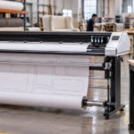
The Velocity Tecnica One is a 49-inch pattern plotter designed for pre-production departments in fashion, textiles, and apparel. It combines accuracy, speed, and ease of use for full-scale pattern printing.
A printed sample makes it possible to:
- compare the file with the original template;
- review dimensions;
- inspect curves;
- verify notches;
- confirm seam allowances;
- perform a physical validation before production
15. Send the File to a Pattern Printing and Cutting Solution
When the pattern must be printed, perforated, or cut on paper, manila paper, cardboard, or other compatible materials, an integrated system can be used.
The Velocity Pattern Plotter Cutter combines inkjet printing with precision cutting and perforation. It is available in 49-inch and 64-inch widths and is compatible with standard industry CAD software.
This system can help:
- print full-size patterns;
- cut templates;
- perforate references;
- reduce handling;
- speed up sample development;
- prepare patterns for production.
16. Use a Digital Cutter to Move the Pattern into Production
Once the digital file has been validated, it can be sent to a compatible digital cutting system.
Velocity offers different options based on material and production volume:
Velocity ProCut-X Single Ply Cutter
Suitable for single-layer materials and applications that require flexibility, customization, and precision.
Velocity Flatbed Plotter Cutter
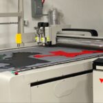
Designed for plotting, marking, and precision cutting on a flat surface, including foam, leather, packaging materials, and other industrial substrates. It can be integrated with existing CAD workflows.
The right choice depends on the material, thickness, production volume, and required operations.
17. Build a Digital Pattern Library
Digitizing creates greater value when files are stored in an organized system.
A basic structure can classify files by:
- customer;
- industry;
- model;
- collection;
- product;
- size;
- material;
- version;
- date;
- approval status.
A consistent naming convention should also be established.
Example:
CUSTOMER_MODEL_PART_SIZE_VERSION_DATE.dxf
It is also advisable to maintain:
- a local backup;
- a server or cloud copy;
- access permissions;
- revision history;
- a master version;
- an approval procedure.
18. Implement Quality Control
Before approving a digital pattern, review:
- dimensions;
- scale;
- symmetry;
- curves;
- notches;
- perforations;
- seam allowances;
- part quantity;
- direction;
- file name;
- version;
- printed or cut validation sample.
Quality control should be completed before producing a full batch.
Common Mistakes When Digitizing Physical Patterns
Taking a Photograph Without Scale References
A standalone image may contain perspective distortion and does not guarantee correct measurements.
Digitizing Damaged Patterns Without Correcting Them
The system will reproduce existing defects if the physical template is not reviewed first.
Failing to Confirm the Pattern Version
An old or unapproved template may be digitized by mistake.
Exporting in the Wrong Format
The CAD software may lose lines, layers, or reference elements.
Failing to Confirm Units
A file may open in inches even though it was created in millimeters, or vice versa.
Sending the Pattern Directly to Production
An initial validation step is always recommended.
Not Reviewing the Vectorization
Shadows, marks, and physical damage may be converted into unwanted lines.
Saving Files Without a Clear Structure
This makes it harder to retrieve the correct version and increases production risk.
Which Industries Can Benefit?
Physical pattern digitizing can be used across several industries.
Fashion and Apparel
For patterns, garments, grading, samples, and production.
Furniture and Upholstery
For covers, seats, backrests, foam, and textile components.
Automotive
For upholstery, carpets, panels, leather, vinyl, and technical textiles.
Footwear and Leather
For cutting pieces, templates, linings, and components.
Specialty Industries
For PPE, composites, marine, aerospace, and technical products.
V-Shoot is designed for industries including fashion, upholstery, automotive interiors, and technical textiles.
Which Velocity Solutions Support This Workflow?
V-Shoot Camera Digitizing System
Captures physical patterns, corrects perspective, vectorizes contours, and exports CAD-compatible files.
VetiGraph CAD
Supports pattern editing, technical adjustments, grading, and preparation for production.
Easy-Plot
Helps connect CAD files with formats used by selected plotters and output processes.
Velocity Tecnica One
Prints full-scale patterns during development and pre-production.
Velocity Vector Marker Plotters
The Vector One, Two, and Four are designed for industrial marker plotting at different production volumes. The Vector Four uses four print heads and is built for high-speed production.
Velocity Pattern Plotter Cutter
Combines pattern printing, cutting, and perforation in a single solution.
Velocity ProCut-X
Bring digital files into automated cutting processes based on material and production volume.
Velocity Flatbed Plotter Cutter
Provides plotting, annotation, and precision cutting across different materials while integrating with CAD workflows.
After-Sales Service and Spare Parts Availability
Pattern digitizing is part of a wider production ecosystem. If the camera, software, plotter, or cutter experiences a technical issue, the entire workflow may be affected.
Before choosing a solution, evaluate:
- installation;
- operator training;
- remote support;
- software updates;
- future compatibility;
- tool availability;
- consumables;
- spare parts;
- response times;
- preventive maintenance.
The long-term value of the technology depends not only on its initial capabilities, but also on the support available throughout its operation.
Conclusion
Learning how to digitize physical patterns for CAD software helps preserve technical knowledge, reduce manual work, and connect product development with marker making, plotting, and automated cutting.
The workflow begins with pattern preparation and continues through capture, vectorization, scale validation, export, CAD editing, nesting, and production output.
Velocity Plotters & Cutters provides solutions for each stage: V-Shoot for pattern digitizing, VetiGraph for design and preparation, Easy-Plot for file conversion, Velocity plotters for printing, and cutters for automated production.
The best implementation will depend on pattern type, dimensions, file formats, workload, materials, and existing machinery.
Before digitizing an entire pattern library, it is advisable to begin with a representative group of templates, validate the complete workflow, and establish clear procedures for review, file naming, storage, and version control.

 EN_US
EN_US  ES
ES