

Table of Contents
- Diagnose Cutting Machine Problems Using a Systematic Approach
- Common CNC Machining Defects and Solutions
- Fix Vibration, Chatter, and Rigidity Problems
- Resolve Calibration, Alignment, and Electrical Issues
- Industrial Cutting Machine Training Requirements
- Preventative Maintenance Checklist for CNC Cutters
- When to Call for Professional Support
- Frequently Asked Questions
Last Updated: October 4, 2026
Diagnose Cutting Machine Problems Using a Systematic Approach
When cutting machines malfunction, production stops. The key to resolving issues quickly is using a structured diagnostic process. A structured diagnostic process helps manufacturers troubleshoot cutting machine issues by breaking the problem into manageable steps, saving time and preventing costly mistakes.
Step 1: Identify the Symptom Category
Describe exactly what’s happening: Is the machine making noise? Are cuts inconsistent? Is the tool breaking? Write down the symptom clearly. Common symptom categories include:
- Tool problems: breakage, dullness, premature wear
- Surface quality issues: burrs, rough edges, poor finish
- Dimensional problems: inconsistent cut lengths, drift, tolerance failures
- Vibration issues: chatter, noise, instability
- Electrical problems: thermal overload, faults, power loss
Knowing your symptom category narrows the search space dramatically.
Step 2: Gather Machine and Material Data
Before testing, collect: machine model and age, current cutting parameters (spindle speed, feed rate, pressure), material type and thickness, runtime since last maintenance, and any recent setup changes. This data rules out obvious causes, a dull tool on new material behaves differently than on a familiar one.
Step 3: Test and Isolate the Root Cause
Make one change at a time, test it, and document results. Start with: cleaning the cutting area, checking coolant flow and temperature, inspecting the tool for damage, verifying calibration and alignment, and adjusting spindle speed or feed rate. If the symptom persists, move to the next test. Record everything in a troubleshooting log.
Common CNC Machining Defects and Solutions
When defects appear in CNC machines, they usually fall into three categories. Understanding each helps you fix cutting machine issues faster.
Tool Breakage and Premature Wear
Why tools break:
- Spindle speed too high for the material
- Feed rate exceeds tool geometry limits
- Inadequate coolant flow or temperature control
- Machine rigidity issues causing vibration
- Tool geometry mismatch for the material type
How to fix it: Reduce spindle speed by 10-15% and test. If breakage stops, speed was the culprit. If not, check coolant flow, coolant removes heat and chips; without it, tools overheat and fail. Verify tool geometry matches your material. If breakage continues after these adjustments, inspect mounting points and spindle bearings for rigidity problems.
Poor Surface Finish and Burrs
Common causes:
- Dull cutting edge
- Feed rate too fast for the tool and material
- Spindle speed too low
- Inadequate chip evacuation
- Pressure roller misalignment (for flat-bed cutters)
Solutions: Replace the tool first, a dull edge produces burrs and rough surfaces. If that doesn’t solve it, reduce feed rate by 20% to allow better chip removal. Check spindle speed next; too slow and the tool tears material. For flat-bed cutters, inspect the pressure roller for misalignment.
Inconsistent Cut Lengths and Dimensional Drift
Root causes:
- Machine calibration drift over time
- Thermal expansion from spindle heat
- Loose mechanical components
- Backlash in drive systems
- Worn guide rails or bearings
How to address it: Recalibrate weekly using built-in CNC routines. Monitor spindle temperature and allow warm-up before precision cuts, thermal expansion moves the cutting head. Inspect mechanical connections; loose bolts and worn bearings compound into dimensional errors. Tighten fasteners and replace worn components.
Fix Vibration, Chatter, and Rigidity Problems
Vibration and chatter reduce precision and shorten tool life. Both signal insufficient rigidity or operation near a natural resonance frequency. Unlike random noise, they follow predictable patterns, identifying which narrows the root cause.
Diagnostic Decision Tree for Vibration Issues
Use this workflow to isolate the source:
Step 1: Characterize the vibration
- Does it occur at all spindle speeds or only within a specific range (e.g., 8,000-12,000 rpm)? All speeds suggests mechanical looseness; narrow range suggests resonance.
- Does vibration increase or decrease with feed rate? Increasing with feed suggests cutting force exciting a natural frequency; reduce feed by 15-25%. Decreasing suggests marginal rigidity; check for loose components.
Step 2: Identify the vibration source
Check these in order:
- Work-holding security: Tighten clamps to full torque. Verify the workpiece sits flat; even 0.005″ of gap causes vibration. Use backing plates for thin materials.
- Tool and spindle balance: Inspect tool runout (over 0.002″ causes vibration). Verify tool holders are fully seated and locked. Confirm tool matches material.
- Spindle bearing wear: Spin at idle and listen for grinding or squealing. Worn bearings allow radial play; contact a technician if suspected.
- Machine base and mounting: Verify level using a precision level. Check mounting bolts are tight. Isolate from nearby equipment with vibration-dampening pads.
- Guide rails and bearings: Movement should be smooth with no binding. Replace if play exceeds 0.005″.
Chatter: Resonance-Specific Troubleshooting
Chatter is rhythmic clicking or squealing at predictable spindle speeds. The cutting force creates a feedback loop: tool deflection changes cutting force, which deflects the tool further.
Note the exact spindle speed where chatter occurs. Increase or decrease speed by 500-1,000 rpm and test; chatter should disappear. This speed range is your machine’s resonant zone for that tool and material.
Solutions for chatter:
- Avoid the resonant speed: Run at 8,500 rpm or 11,500 rpm instead of 10,000 rpm. Most machines have multiple usable speed ranges outside the resonant zone.
- Increase cutting force: Increase feed rate by 10-20% to stabilize the tool. Monitor surface finish; if it worsens, you’ve increased feed too much.
- Reduce tool overhang: Use the shortest tool holder and length that allows clearance. Reducing overhang by 0.5″ can shift resonant frequency outside your operating range.
- Change tool geometry: Carbide tools are stiffer than high-speed steel and sometimes eliminate chatter. Consult your tool supplier for recommendations.
- Dampen the spindle: Spindle dampers reduce vibration transmission. Discuss specialist modifications with your machine manufacturer.
Environmental and Operational Factors Affecting Vibration
Vibration worsens under conditions that reduce stiffness or increase external disturbance: cold spindles are stiffer (allow 15-30 minutes warm-up), unstable power causes servo oscillation (install a voltage regulator if needed), nearby heavy machinery transmits floor vibration (isolate with elastomer pads), and coolant temperature affects tool stiffness (maintain 65-75°F for most systems).
When Parameter Adjustment Isn’t Enough
If vibration persists after adjusting speed, feed, tool overhang, and work-holding:
- The machine likely has worn bearings, loose structural components, or a cracked base.
- Contact a service technician for spindle inspection and structural assessment.
- Continuing to run a vibrating machine accelerates wear and compounds the problem.
Resolve Calibration, Alignment, and Electrical Issues
Machine calibration and electrical health determine whether cuts meet specifications.
Machine Calibration and Alignment Checks
Calibration drift causes dimensional errors that compound over time.
Check calibration weekly on machines running daily. Most CNC systems include calibration tools in their software. Run them and document results.
Verify mechanical alignment using a dial indicator if your machine allows it. Check that guide rails are parallel and the cutting head moves smoothly without binding.
Inspect pressure rollers on flat-bed systems. They should contact the material evenly. Uneven pressure causes inconsistent cuts. Adjust or replace rollers if necessary.
Thermal Overload and Electrical Fault Detection
Thermal overload occurs when spindle or drive motors get too hot. The machine shuts down to prevent damage.
Prevention:
- Ensure adequate cooling system operation
- Check that air intake and exhaust vents are clear
- Monitor ambient temperature in the cutting room
- Allow cooldown time between heavy production runs
- Replace thermal paste on spindle bearings annually
Electrical fault detection: Most CNC machines display error codes when electrical problems occur. Check your machine’s manual for code meanings. Common issues include:
- Loose electrical connections
- Worn motor brushes
- Failed capacitors
- Damaged servo drives
If you see repeated electrical errors, contact a service technician. Electrical repairs require specialized knowledge and equipment.
Industrial Cutting Machine Training Requirements
Operators need proper training to use cutting machines safely and effectively. Untrained operators cause breakdowns, waste material, and create safety hazards.
Training should cover:
- Machine startup and shutdown procedures
- How to load and secure materials
- Basic parameter adjustment (speed, feed, pressure)
- Tool changing and inspection
- Recognizing abnormal sounds or vibrations
- Emergency stop procedures
- Basic troubleshooting steps
New operators should shadow experienced staff for at least one week before running machines independently. Hands-on experience matters more than classroom instruction.
Refresher training helps. Even experienced operators benefit from reviewing best practices annually. As machines age or materials change, techniques evolve.
Preventative Maintenance Checklist for CNC Cutters
Regular maintenance prevents most cutting machine issues. A preventative maintenance program reduces downtime and extends equipment life.
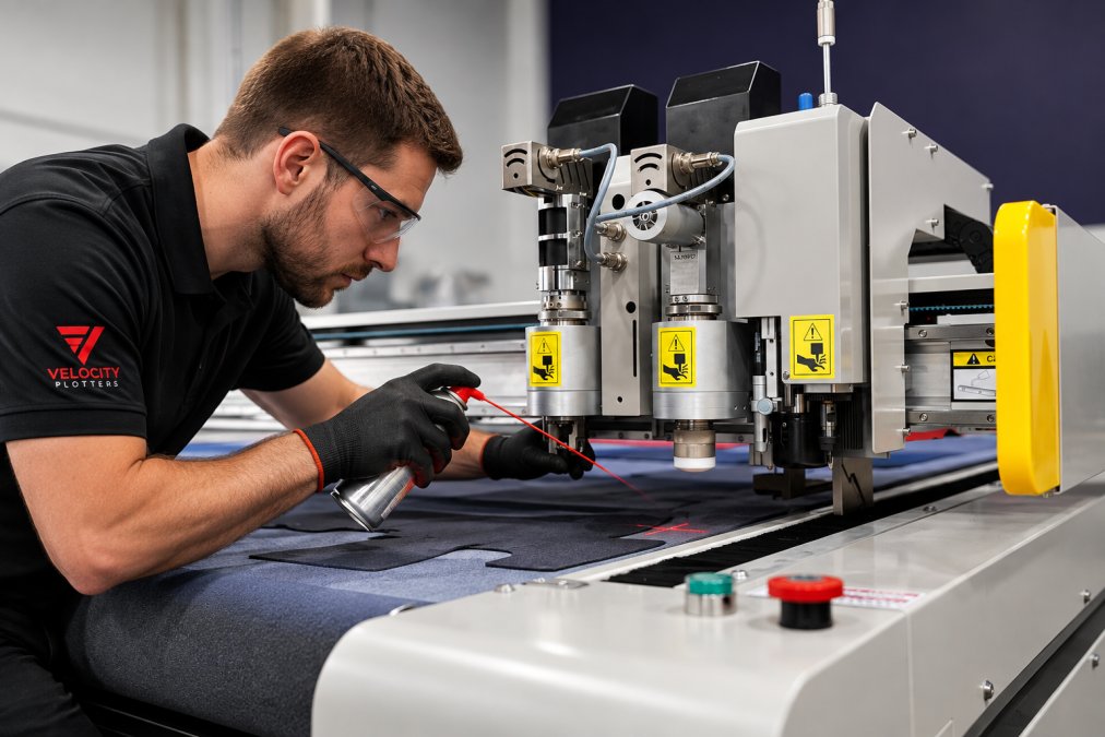
Daily and Weekly Maintenance Tasks
Daily (before production starts):
- Inspect the cutting area for debris or obstructions
- Check coolant level and top off if needed
- Verify spindle runs smoothly without unusual noise
- Confirm all work-holding clamps are secure
- Test the emergency stop button
Weekly (after heavy production days):
- Clean the cutting bed and remove accumulated chips
- Inspect tool holders for damage or wear
- Check all electrical connections for looseness
- Verify guide rails move freely without binding
- Document any unusual sounds or vibrations
Monthly and Quarterly Inspections
Monthly:
- Replace coolant if it shows signs of degradation (discoloration, odor, foam)
- Inspect spindle bearings for wear or noise
- Check pressure rollers for even contact
- Test all safety interlocks
- Review maintenance logs for trends
Quarterly:
- Perform full machine calibration
- Inspect and clean air filters
- Check thermal management system operation
- Lubricate moving parts per manufacturer guidelines
- Replace worn consumables (seals, brushes, thermal paste)
Keep detailed records. A maintenance log shows when problems started and what fixes worked. This history helps you predict failures before they happen.
|
Maintenance Task |
Frequency |
Time Required |
Impact |
|---|---|---|---|
|
Debris removal and coolant check |
Daily |
10 minutes |
Prevents tool breakage and overheating |
|
Coolant replacement |
Monthly |
30 minutes |
Maintains surface finish quality |
|
Machine calibration |
Weekly |
20 minutes |
Ensures dimensional accuracy |
|
Spindle bearing inspection |
Quarterly |
45 minutes |
Detects wear before failure |
|
Full system check |
Quarterly |
2 hours |
Identifies emerging issues |
When to Call for Professional Support
Some problems require specialist expertise. Knowing when to call saves time and prevents damage.
Contact a service technician if:
- Electrical errors persist after basic troubleshooting
- Spindle bearings make grinding noises
- Calibration drifts despite weekly recalibration
- Vibration continues after parameter adjustment
- Hydraulic or pneumatic systems leak
- The machine shuts down unexpectedly
Professional technicians have diagnostic equipment and spare parts. They can identify problems that field troubleshooting can’t resolve. A service visit costs less than extended downtime.
Velocity Plotters provides world-class technical support to ensure cutting systems run reliably.
Troubleshooting cutting machine issues becomes routine once you understand the diagnostic process.
Frequently Asked Questions
What are the most common causes of precision loss in industrial cutting machines?
Precision loss typically stems from tool wear, spindle runout, misalignment, or thermal growth. Tool geometry degradation reduces cutting edge sharpness, increasing feed rates and causing dimensional drift. Spindle runout—radial movement during rotation—compounds this. Temperature changes in the cutting zone and ambient conditions cause material and machine expansion. Loose fasteners, worn bearings, and calibration drift also contribute. Regular tool inspection, spindle maintenance, and environmental control mitigate these issues.
How often should industrial cutting machines undergo preventative maintenance?
Daily tasks include checking coolant levels, inspecting for blade obstruction, and verifying spindle operation. Weekly maintenance covers feed wheel and pressure roller inspection. Monthly checks address calibration verification and rigidity assessment. Quarterly inspections examine thermal stability and electrical connections. The frequency depends on machine type, cutting parameters, and material volume. High-speed CNC operations demand more frequent attention than low-speed equipment. Follow manufacturer guidelines and adjust based on downtime history.
What are the signs that a cutting blade or tool needs immediate replacement?
Replace tools when you observe chatter marks on the surface finish, increased cutting force, visible chipping or flaking on the cutting edge, or thermal discoloration. Burrs and rough edges indicate dulled geometry. If feed rate or spindle speed adjustments no longer improve surface quality, tool wear is likely severe. Inconsistent cut lengths across a batch signal tool degradation. Preventative replacement before catastrophic failure reduces scrap and machine stress. Track tool life by cut count or hours to establish replacement schedules.
How can software calibration errors impact cutting machine performance?
Calibration errors in CAM software or machine controllers cause dimensional inaccuracy, offset cuts, and material deformation. If programmed feed rates don’t match actual machine capability, tool breakage or poor surface finish results. Spindle speed mismatches create excessive heat or insufficient cutting force. Coordinate system errors lead to blade obstruction or off-pattern cuts. Thermal compensation algorithms must account for machine expansion during operation. Regular verification of software settings against machine specifications and test cuts prevents costly scrap and downtime.





 EN_US
EN_US  ES
ES